DXF Plot/Print Options
You can specify the name of the output file for the dxf plot information. Use the Browse button to select the
directory in which the output file will be placed.
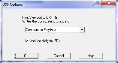
The lines which are written to the output file can be:
Polylines – a series of X,Y points forming a single line. The line curvature will be added by Autocad.
Normal Lines - Straight Lines – between each X,Y point.
You can optionally include heights on the points.
Note:
There are two methods for writing job information to a DXF file.
1. The menu option Conversions/DXF/Write Job writes all the job data to a DXF file in 3d real world co-ordinates.
2. The menu option File/Print/DXF File which treats the DXF file like a printer/plotter and writes the scaled data in
plan mm. This option is designed for producing a drawing or plan in Autocad.
To export the job in real world co-ordinates use the menu option Conversions/DXF/Write Job. Tick the
'All' box if all the data in the job is required to be exported. Alternatively un-tick the 'All' box and press
the Select Points/Layers button. This screen allows you to select which layers and which points will be
written to the DXF file. Note that both the layer and points range must be selected to write the points to the
DXF file. If the points are selected but the points layer is not selected, the points will not be included in the file.
Point symbols will be written as 'Blocks' into the DXF file and will be used at each point which uses that
symbol. The layers and layer attributes like colours and linetypes in the DXF file will be the same layer names
as used in the job, except that the layer names may be changed slightly to remove spaces and some illegal characters
which are not allowed by Autocad.
If the 3d box is ticked, each data point or string will be written in three dimensions. Contours are written
as smoothed polylines. Triangles are written as 3d 'faces' and can then be easily used for 3d surface modelling.
The layer code translation file allows the user to translate the layers, colours and line types used in the
job to a different set of layers, colours and linetypes, perhaps to conform to a standard required by the customer.
A translation file can be constructed by the user using a text editor. See the online help entry under 'Layer Translation'
for details on how to format the layer translation file.
Print to DXF File - this option writes a DXF file like a plan drawing in mm. The user is requested to
select a viewport so that the program will know the plot scale and extents of the plan.
Fonts
You can control whether fonts are written to the DXF file by a config variable in GeoSurvey_config.xml
or similar config file at about line 54. See <dxfFonts> setting, set to No to eliminate fonts.
This means that all text in the DXF file will default to 'TEXT' font in Autocad.